JFET STRUCTURE AND WORKING
JFET: A thin semiconductor bar with a gate controlling current flow by pinching a channel.
0
111
- One of the most basic kinds of field-effect transistors is the JFET, which stands for Junction Field Effect Transistor.
- JFETs, on the other hand, are voltage-controlled devices, not bipolar junction transistors. Most of the current flow in a JFET comes from charge carriers.
- On the other hand, in BJTs, both minority and bulk charge carriers are responsible for the current flow.
- JFETs only allow current to move in one direction because most of the charge carriers are responsible for it. In 1953, the first model of a junction field-effect transistor that worked was made.
The JFET Construction

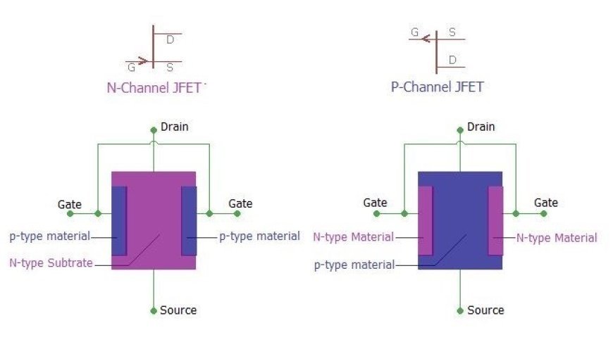
- In an N-channel JFET, the material is P-type and the substrate is N-type. In a P-channel JFET, on the other hand, the material is N-type and the substrate is p-type.
- JFET is made up of a long slot filled with semiconductor material.
- At each end of the semiconductor tubes, there are ohmic contacts that can be used to connect the source and sink.
- A JFET with a lot of positive charges is called a P-type JFET. An N-type JFET, on the other hand, has a lot of negative charges.
JFET Operation
- Let's look at how a JFET works by comparing it to a yard hose pipe.
- If there is nothing in the way of the water flowing through a garden hose pipe, it runs easily.
- But if we squeeze the pipe a little, the water moves more slowly. This is the exact way a JFET works. In this case, the tube is like a JFET and the flow of water is like a current.
- We could control the flow of current by building the current-carrying path the way we wanted.
- Electricity can run freely through the channel when there is no voltage between the source and gate.
- If you apply the polarity that makes the P-N junction reverse biased, the channel gets narrower because the depletion layer grows. This could put the JFET in the cut-off or pinch-off area.
JFET Types
A JFET can be broken down into two groups based on where the current flows:
JFET with n-channel
JFET with a p-channel
- Whether holes or electrons are responsible for the flow of current determines the type of class.
- The following picture shows the circuit symbol for an n-channel JFET and its diagram.

Here is a picture of a p-channel JFET's design and its circuit symbol.

Uses for Junction Field Effect Transistors
- The JFET can be used as a switch, a chopper, a buffer, in oscillatory circuits, and in cascade amplifiers.
JFET Advantages
Here are some of the benefits of JFET:
- The junction field effect transistor (JFET) has a high impedance and low power usage.
- JFETs can be made smaller, which means they take up less room in circuits.
JFET Disadvantages
Here are some bad things about JFETs:
- The result of its gain and bandwidth is low.
- As the frequency goes up, input from the internal capacitor changes how well the JFET works.