BAND PASS FILTER
Bandpass filters: Isolate your signal, conquer noise.
0
74
Band Pass Filter
- In electronic engineering, a band-pass filter is a circuit that lets data run between two frequencies while separating them at other frequencies. There are different kinds of these filters.
- One type, called an active band pass filter, can be powered from the outside and have active parts like integrated circuits and transistors.
- Also, some filters use any kind of power source and passive parts like capacitors and inductors. This type of filter is called a passive band-pass filter.
- These filters can be used on both wireless emitters and listeners.
- A BPF can be used in an emitter to get the output signal's frequency down to the bare minimum so that it can send data at the desired speed and format.
- In the same way, this filter in a receiver lets signals in a preferred frequency band be read while blocking signals at frequencies that aren't needed. It is possible for a BPF to improve the signal-to-noise ratio (S/N) of a sensor.
Band-Pass Filter Circuit

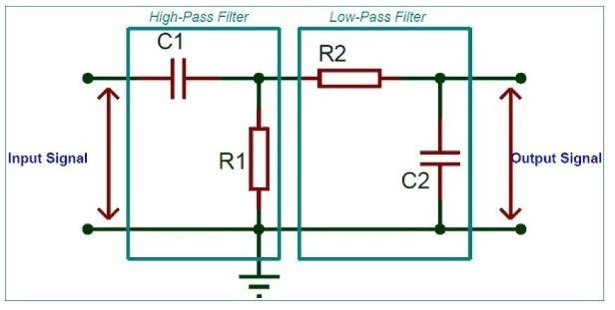
- Below is an RLC circuit that shows the best way to make a band-pass filter circuit. You can also make this filter by combining an LPF and an HPF.
- Bandpass is used to describe a type of filter or a process for screening in BPF. It is different from a passband, which refers to the real part of the affected range.
- It is a completely level passband because an ideal bandpass filter doesn't have gain or attenuation. That will completely cut down all bands outside the passband.
Band-Pass Filter Circuit
- In real life, the bandpass filter isn't perfect because it doesn't completely block out sounds that aren't in the desired range.
- In particular, there is a region just outside the suggested pass band where frequencies are weakened but not thrown away. This is known as the filter roll-off, and it is generally given in decibels (dB) for each octave or decade of frequency.
- In general, the design of the filter tries to make the roll-off as small as possible, which lets the filter do the design that was suggested.
- Most of the time, this can be done at the cost of passband ripple or stopband ripple.
- The difference between the top frequency and the lower frequency is what the filter bandwidth is.
- The form factor is the percentage of bandwidths that can be estimated with two different attenuation values to find the cut-off frequency.
- In this case, a form factor of 2:1 at 20/2 dB means that the bandwidth calculated between frequencies at 20 dB attenuation is twice that calculated between frequencies at 2 dB attenuation.
- Optical BPFs are often used in photography and for lighting in the theatre. These filters take the shape of a clear-coloured film or sheet.
- This is a bode plot, also known as a frequency response curve, that shows how the band-pass filter works.
- The output goes up at a rate of +20 dB/decade (6 dB/Octave) until the frequency hits the "lower cut-off" point ̒L.
- This weakens the signal at low frequencies. In this case, the output voltage is again 1/√2 = 70.7% of the value of the input signal, or -3 dB (20*log(VOUT/VIN)) of the input.The output stays at its highest level of gain until it hits the "upper cut-off" point H.
- At this point, the output drops at a rate of -20 dB/decade (6 dB/Octave), which weakens any high-frequency sounds.
- The "Centre Frequency" or "Resonant Peak" value is the point where the output gain is highest.
- It is usually the geometric mean of the two -3 dB values that are between the lower and upper cut-off points. r 2 = (upper) x (lower) is how you figure out this geometric mean number.
- A band-pass filter is a second-order (two-pole) type of filter because it has "two" reacting components in its circuit structure. This means that the phase angle is twice as big as it was for first-order filters, or 180°.
- Up to the middle or resonant frequency, where it becomes "zero" degrees (0o), or "in-phase," the phase angle of the output signal is +90o ahead of that of the input signal.
- As the output frequency rises, it changes to lag the input by -90o.
Electrical Equivalent of a Band Pass Filter
Specification of the Band Pass Filter

Pass-band
- The most important thing to know about a bandpass filter is its operating passband.
- Low-frequency cut-off: this is the frequency where the filter starts to ignore low-frequency signals. Any frequency below this one will be less strong than the pass band.

- Upper cut-off frequency: This is the filter's highest passband frequency. As you move up in frequency, the filter will lose more of its power after this point.
Applications of Band Pass Filters
- Bandpass filters are used for many things, like on smartphone screens.
- Modern smartphones can connect to various LTE bands that are in use by phone companies all over the world.
- In the transmission section of each handset, there are several band-pass filters that make sure it works well in all frequency bands, from 700 MHz to 2700 MHz.
- Higher frequency bands in the sub-6 GHz range are needed for 5G technology to be used.
- Some gadgets that support 5G use powerful bandpass filters to improve the signal quality.
- Bandpass filters help Wi-Fi routers pick out signals more clearly and block out other noise from the environment.
- Bandpass filters are used to choose the mid-range frequency in high-definition audio devices.
- Bandpass filters are used in satellite technology to pick the right range.
Bandpass filters are used in the gearbox parts of self-driving cars. - A lot of IoT devices use bandpass filters to make the range of signals they receive more selective.
- Bandpass filters are also often used in RF test labs to create fake test conditions for a variety of uses.
- High-power units that send and receive signals use high-pass filters to keep other frequency bands from interfering with their work.